
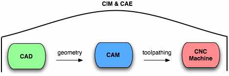
The figure above is a simplified software workflow for CNC machining. The process starts with Computer Aided Design (CAD) software. This is where the geometry is created for the part to be machined. The part file is then sent to the Computer Aided Machining (CAM) program where a toolpathing strategy is applied. Once toolpathing is completed, the file is sent to the CNC machine. The entire manufacturing process is run by Computer Integrated Manufacturing (CIM) software with supporting services provided by Computer Aided Engineering (CAE) applications.
There is a plethora of different software applications used to support CNC machining. Beyond that, there are even more possible combinations of the different applications. Each software package is specifically tailored to the machine. The software available can be grouped by functionality into the following broad groups:
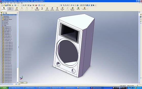
CAD software allows an engineer to draw geometry using a computer. The drawing can be a part, an art design, a building, or anything else that needs to be built or machined. The drawing on the screen is translated into digital code that can then be read in the CAM software.
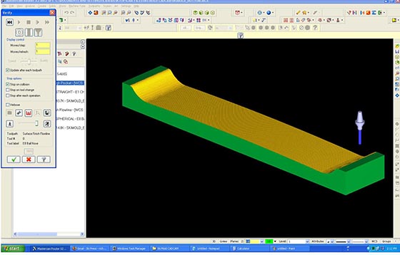
CAM programs allow you to generate the necessary toolpaths for successful machining based on the geometry created in the CAD program. Toolpathing will determine which tool is used and how it is used by the machine. Once completed, the CAM file is post-processed. Post-processing involves turning the toolpath commands into machine code called G-code. Most CAM programs can also allow us to preview what the machine will do. The simulation identifies any possible collision problems and estimates the total machining time required.
From a bird’s-eye-view, CIM runs the day-to-day operations of the factory such as Inventory, Purchasing, Production, etc. They optimize process flows and do data collection for operational analysis. These systems are often very comprehensive and expensive, but can pay their way back through automation and optimization.
CAE is a general term for the use of information technology by Engineers. Engineers will use CAE software for a wide variety of tasks such as finite element analysis, production simulation, diagnosis, and repair. They assist the Engineer in making informed decisions. (1)